Honda has created a new division, Fastport, to manufacture eQuad delivery vehicles to simplify last-mile package deliveries. The vehicles have four wheels, pedal-by-wire rider input, have a 250 Watt drive motor , a top speed of 12 mph and come two sizes. The power and speed numbers are very close to European eBike requirements of 15mph and 250 Watt motor.
There is a good and a bad side to this news.
The good side is, if you allow the top speed to increase to 15mph, the the Fastport eQuad qualifies as a European eBike. If the Fastports can be ridden legally on US bikeways, then these vehicles allow quads to break into the US eBike regulations, which previously only allowed three wheels.

The bad side is that Honda has assumed that the bike lanes can handle a vehicle which is 4 feet wide and over 12 feet long, without impeding the bicyclists that the lanes were created for. Considering that the eQuads will probably stop on the bike ways to deliver their packages, their obstruction may require the normal cyclists to move into the traffic lanes to go around the eQuads. Obliviously putting the cyclists at risk.
There are a number of European manufactures producing similar vehicles. Many have widths of less than 3 feet and lengths less than 10 feet. These vehicles would be much more compatible with bike lanes.
The TMQ delivery quad from ALSO, an American product associated with Rivian E Vehicles and used by Amazon for the "last-mile-deliveries".


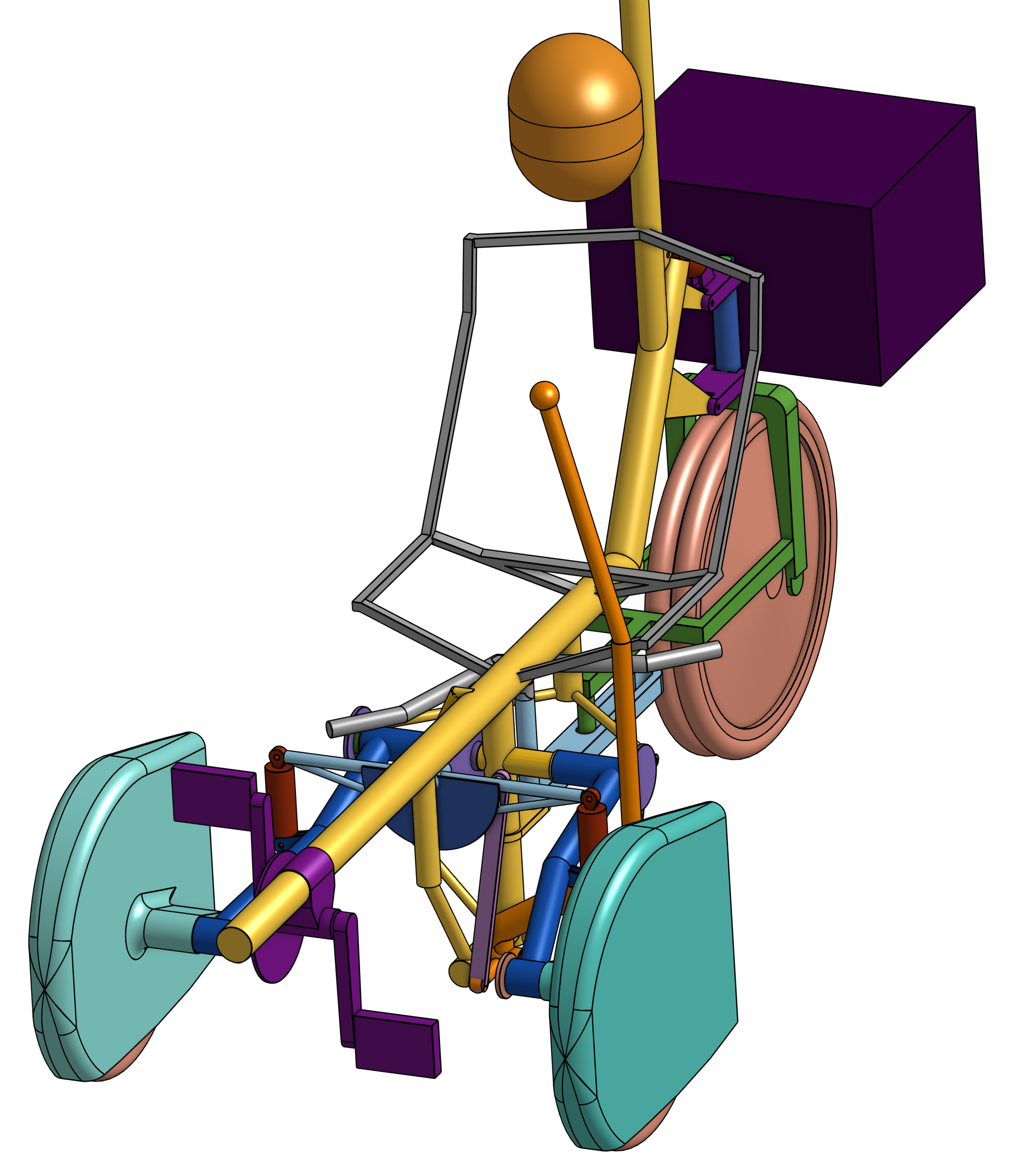
Now all the quads I have seen on the internet use pedal by wire. There is no mechanical connection between the pedals and the drive wheels. This can be very adventageous when the pedal-generator is at the front of the vehicle and the motor to drive the wheels is at the back of the vehicle. Since the delivery load is toward the back of the vehicle, most vehicles are rear-wheel drive.
Traditionally, pedaling on a pedal-by-wire vehicle is not as smooth as a traditional chain drive. This is because the legs produce power in pulses, not continuously. The system inertia (read bicycle mass) smooths out these pulses to match the constant nature of the pedaling resistance. The pedal generator has very little inertia and the pedaling ends up being jerky. There must be some means of resolving the lack of smoothness electronically, but I am not aware of any ebikes using it.
The other issue has been there is a lag between pedaling and moving when getting started.
All that being said, there are many options available for electronic gear changing and integrating battery power into pedaling for vehicle propulsion. Pedal by wire also lets the rider back up by pedaling backwards.
Now, cargo ebikes and etrikes are not new to last-mile deliveries. But ebikes are limited as to how much cargo they can carry and etrikes need excessive widths if they have a safe roll-over resistance when cornering. Both vehicles typically do not have inclement weather protection.
What quad vehicles offer is significantly larger cargo capacities and 50% greater roll-over resistance when compared to etrikes of equal width. And inclement weather protection.
I think that quad delivery vehicles are a very good thing, breaking into the three-wheel-max ebike prohibition in North America. They open the door to importing European velomobiles into the US and Canada.
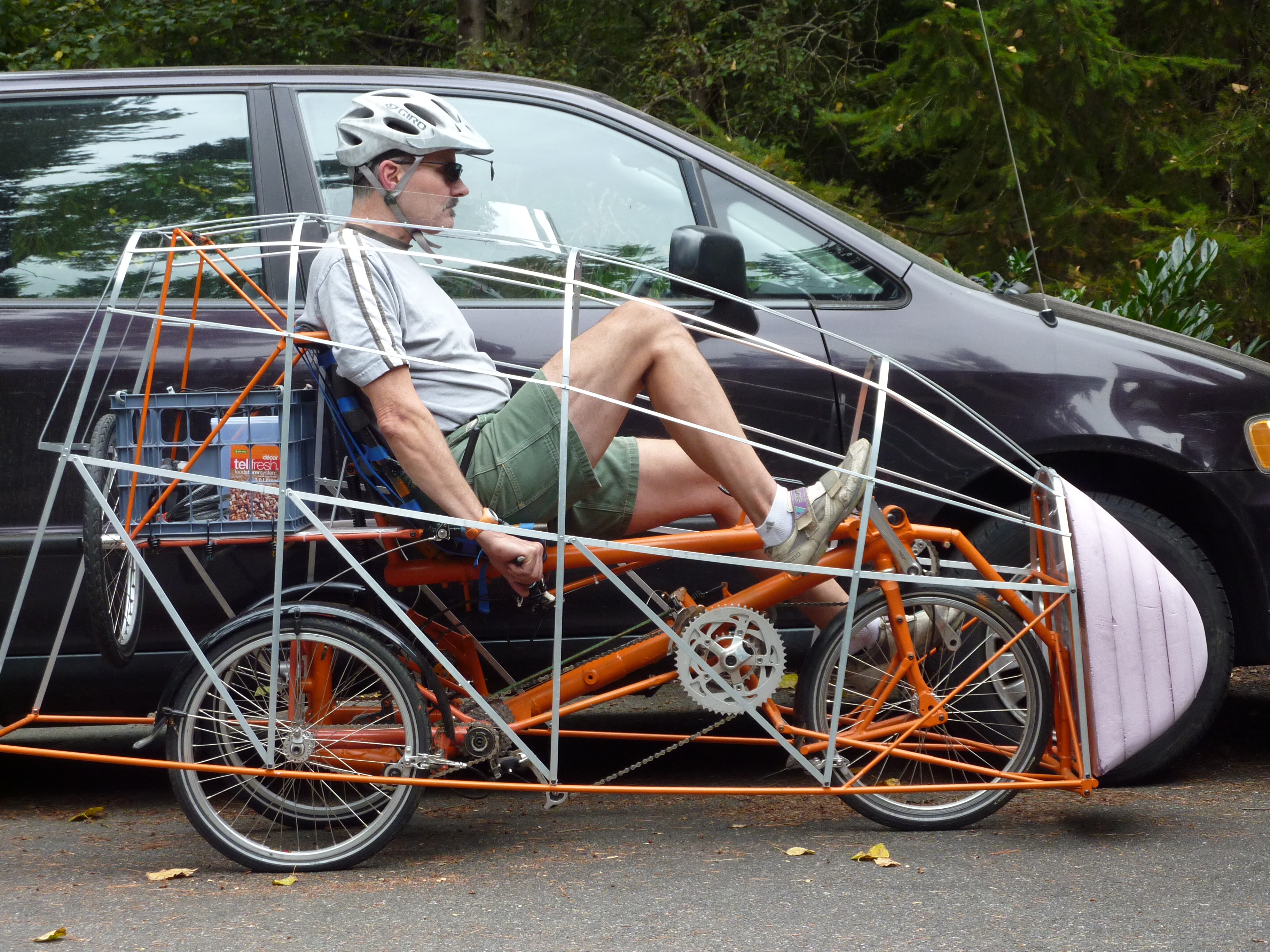
But I think there needs to be an additional requirement to the 15mph speed and the 250W requirements, and that is limiting the delivery quad width. The larger Honda Fastport vehicle has a width of 48". In the second picture above, it is clear that this vehicle is obstructing the bike path for regular cyclists. This is going backwards when it comes to making cities eco friendly to alternative means of transportation.
I propose limiting quad delivery vehicle widths to 34"(860mm). This would allow the quads to pass through common barriers of 36" and most of the European quads meet this requirement. The smaller Honda Fastport has a width of 39.4"(1000mm) so it would only have to be made 4" narrower.
Hephaestus


.jpg)


.jpg)