


Those of you that have viewed my blog more than a few times recognize my fascination with the Pedicar, invented by Robert L. Bundschuh, a 38 year old ex-Gyrodyne aircraft engineer and his coworker, Lionel Martin, in 1972.
https://www.youtube.com/watch?v=xtlErX6nkY4
The level of technical execution and the production quality were very high. The Pedicar only used tires, rims, spokes, mirrors and reflectors from conventional bicycle parts. The rest of the parts were designed expressly for the vehicle. This was far beyond the garage-shop level of production shown by most efforts of this type. The design details represent some very visionary thinking, when the International Human Powered Vehicle Association was three years in the future.
And then there is the video. I get so excited whenever I watch it. I have seen nothing else that conveys the potential that human power has for transportation as well as the Pedicar commercial. Even though the traffic environment that is depicted is very benign and the vehicle itself would be significantly different if designed based on current human-powered-vehicle knowledge, you get a tantalizing glimpse of an eco-friendly future.
There seems to be a renewed interest in the Pedicar as of late, but the details of the vehicle have not been gathered in one recent article, so I thought I would give it a shot. I had some of the original material from the mid 1970’s and I also obtained a copy of the patent (3871243) from Google Patents. Having some experience reviewing patents, I felt I would distill the salient features of the design for public consumption.
The most descriptive articles I have found were by A.J. Hand in the August 1973 issue of Popular Mechanics and by Bruce Wennerstrom in the February 1973 issue of Mechanix Illustrated. They cover most of the details. I will be using photos from these articles and the patent art add a bit more detail to Hand’s and Wennerstrom's observations.


The Pedicar weighed 125 lb., the wheelbase was 58” and the track was 36”. The overall length was 82".
THE CHASSIS

 The chassis is a weldment made up of square and round aluminum tubing. 278 is the longitudinal spine which appears to be 2” square tubing. 279 is a round tube that supports the steering pivots. 280 is a round tube that supports the axle bracket plates 425. 281 and 282 are square tubes that support the pedal-lever pivots and the steering column. Tubes 278 and 281 contain large holes which are primarily for lightening. Since the Pedicar has no provision for wheel suspension, the holes could also reduce the torsional stiffness of tube 278 and allow tubes 279 and 280 to rotate relative to each other, thereby providing a means to keep all four wheels in contact with uneven road surfaces.
THE LEVER-DRIVE TRANSMISSION

 The top of the left-hand pedal lever is attached to a pivot on tube 282 of the chassis weldment. The bottom of the pedal lever is attached to a cable that extends backward to wrap over an idler 308 and then to a cable reel 309 (drive pulley in the above picture) which is, in turn, attached to the input shaft of the gearbox through a one-way clutch. Attached between the cable drum and the gearbox housing is a constant torque spring. As the pedal is moved forward, the cable is unwound from the reel and this rotates the input shaft of the gearbox. At the same time, the constant –torque spring is wound up. When force on the pedal is removed, the constant-torque spring pulls the pedal back to its rearward-most position. The bottom of the pedal lever contains a rocking pedal that allows the foot to remain in a comfortable position as the pedal lever rotates. The bottom of the pedal has a lip that supports the driver’s foot and prevents it from slipping off the pedal. The right-hand pedal lever uses a similar arrangement.
There is no mechanical connection between the two pedal levers. As a result, the pedals can be pushed alternately, together or either one only. There are bumpers to limit forward and rearward travel located on the chassis at tube 282.
THE GEARBOX
By far, the bulk of the verbiage in the patent describes the gearbox. I will try to convey the essence of its function in an abridged fashion. I will use the term gearbox to differentiate the speed-changing mechanism from the lever-drive transmission proper.
The gearbox and rear-wheel drive can be considered to be made up of three parallel shafts. The first shaft is the input shaft, and it supports the cable reels. It is the shaft that is rotated as the pedal lever is moved forward. The shaft is support on both ends by ball-bearings that are held by the gearbox housing. The second shaft is the output shaft. It is also supported on both ends by ball-bearings that are held by the gearbox housing. There are six gear sets that are capable of coupling the input and the output shafts. Five of the gears sets are made up of two gears, one gear on the input shaft and one gear on the output shaft. These five gears sets produce the five forward speeds of the gearbox. The sixth gear set has three gears. One gear is on the input shaft, one gear is on the output shaft and there is an idler gear that connects the input and output gears. The idler gear reverses the direction the output shaft rotates and, as a result, this sixth set of gears produces the reverse gear of the gearbox. The third shaft is actually two pieces and each piece supports a rear wheel. These shafts are supported by one bearing that is part of the gearbox housing and one that is carried by the axle bracket plate 425. The output shaft has two more gears that mate with the gears on the axles. The gears are attached to the output shaft by one-way clutches.
The gear sets are arranged as follows: reverse, a gap for neutral, followed by first through fifth. They fit loosely and can rotate freely on their respective input and output shafts. The gears are constrained axially by anti-friction thrust washers, spaced between the adjacent gears. The internal diameters of the gears have multiple notches to accept a sliding spring-loaded key that can selectively lock any set of gears to their respective input and output shafts and provide input to output coupling. For strength, the width of the key, axially along the shafts is equal to the width of one gear plus the width of slightly less than two of the thrust washers. The input and output shafts are slotted to accept the sliding keys and those slots extend from under the reverse gear to under the fifth forward gear. When the key engages a gear, the spring loading takes up the slop between the gear and the shaft, and thus, rigidly coupling the gear to the shaft. By using two keys, one for each shaft, as opposed to using a key on only one shaft and rigidly coupling one set of gears to the other shaft, friction is drastically reduced, because only one gear pair is rotating at a time.
The shift lever moves cables that translate the keys together, so both members of the gear set are locked simultaneously. If the gear proportions on the patent are accurate, then the high-gear ratio is 6.8 times the low-gear ratio and the gear ratios increase 60% per shift. Gears could be shifted smoothly while the vehicle was stopped or moving without any difficulty.
The stops for the most rearward position of the pedal levers, in combination with the one-way clutches that the cables drive, prevents the vehicle from being rolled backward. Since the vehicle is heavy enough to make lifting prohibitive, at a minimum, the ability to disengage the drive from the wheels was necessary to push the vehicle backward. Adding a reverse gear to the disengagement mechanism was a logical addition.
The stops for the most rearward position of the pedal levers, in combination with the one-way clutches that the cables drive, prevents the vehicle from being rolled backward. Since the vehicle is heavy enough to make lifting prohibitive, at a minimum, the ability to disengage the drive from the wheels was necessary to push the vehicle backward. Adding a reverse gear to the disengagement mechanism was a logical addition.
The operation of the reverse gear results in only one of the rear wheels being driven. Even with this apparent simplification, the gear shifting is more complex than just coupling the reverse gear sets to there respective input and output shafts. The gear connecting the output shaft to the wheel shaft for the non –driven wheel must be disengaged, and the one-way clutch of the gear that connects the output shaft to the driven wheel must be locked up.
STEERING AND BRAKING
Steering is controlled by handles, 289, attached to a semi-horizontal shaft that is radially supported in frame tube 282. The steering shaft is made up of two concentric tubes, 290 and 296. Shaft 290 can be telescoped within shaft 296 to adjust steering handle position, to accommodate different size riders. In addition, in the event of a frontal impact where the driver’s chest collides with the handles, shaft 290 can collapse within shaft 296 to absorb impact energy. The near-vertical motion of the output lever on the steering shaft is converted to horizontal motion of the bellcrank mounted on chassis tube 279 by two interconnected four-bar linkages that are arranged at 90deg. to each other. The bellcrank is coupled by tie-rods, 292, to the two pivoting axle supports, 291, located at the outer ends of chassis tube 279.
The gears attached to the axle shafts 392 & 395 are large enough in diameter to act as rotors in a disk-brake system. The dual-calipers for that system pivot about mounts that are attached to the chassis tube 278. The brake pedal that actuates both disk brakes is located in the middle of chassis tube 278, just behind chassis tube 281. There is also a pull-knob below the steering column that actuates the disk brakes for parking purposes.
BODY
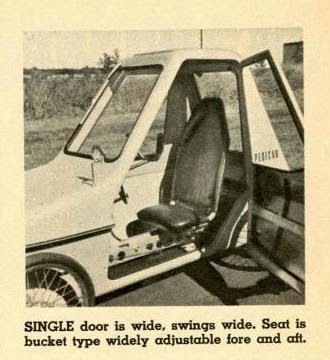 The body is made up of five pieces. The bottom pan, 433a, the top cover, 433b, and the door are thermoformed plastic. The PM article says ABS. Another article says Cycolac and someone recently found an abandoned Pedicar where the body was fiberglass. The front windshield material is Abcite. The rear window is hinged at the top and is removable. It is probably a transparent plastic like the windshield. The bottom pan is bolted to the chassis and supported by flexible gaskets in four places: both sides of chassis tube 279 and both axle bracket plates 425. The top cover has a lip that hangs over the rim of the bottom pan to keep water from leaking into the vehicle and these two pieces are screwed together around the periphery of the body.
 SEAT & ACCESSORIES

The seat is high-backed and well padded. The height is intended to provide whiplash protection.It rests on chassis tube 278. It can be slid forward and backward to adjust to the rider’s leg length and it can be tilted about a pivot below its base as well. There is a storage compartment behind the rear seat that can hold up to four bags of groceries and a narrow jump seat that will allow a child to sit behind the driver.
Standard accessories are seatbelts, a headlight, a rearview mirror, hub mounted reflectors, a windshield wiper and door and hatch locks. Optional accessories are a sunroof, a horn, a radio, a speedometer and turn signals.
So that covers the technical features of the Pedicar. If you prefer to skip my technical editorializing, you can stop reading here.
PEDICAR POSTMORTUM
And how well did the Pedicar work? A. J. Hand of Popular Mechanics had complaints about the lever-drive transmission and the gearbox. He found that the linear motion severely limited his pedaling cadence. He felt that the pedal travel was too long and when he got to his cadence limit and shifted to the next gear, pedal resistance was too high.
With the effort of jogging Wennerstrom could cruise at about 15mph and hit a top speed of 18mph. A 28mph. downhill run was memorable. Despite Hand's complaints, the Pedicar was capable of climbing very steep grades. The combination of not having to balance, the inability of the Pedicar to roll backwards and an extremely low gear allowed Dr. Paul Dudley White, President Eisenhower’s cardiac surgeon and noted bicycle advocate, to pedal the Pedicar up a 21% grade at the age of 84.
By pressing both pedals simultaneously, it was possible to hop the Pedicar over an 8" curb.
With the effort of jogging Wennerstrom could cruise at about 15mph and hit a top speed of 18mph. A 28mph. downhill run was memorable. Despite Hand's complaints, the Pedicar was capable of climbing very steep grades. The combination of not having to balance, the inability of the Pedicar to roll backwards and an extremely low gear allowed Dr. Paul Dudley White, President Eisenhower’s cardiac surgeon and noted bicycle advocate, to pedal the Pedicar up a 21% grade at the age of 84.
By pressing both pedals simultaneously, it was possible to hop the Pedicar over an 8" curb.
The problems encountered by Mr. Hand are common with lever-drive transmissions. Bundschuh felt, like a lot of others before and after him, that since the leg could produce a constant unidirectional force, applying that force to a rotary crank did not produce a constant torque. For a constant force, the average output torque is 2/Pi or 64% of the peak torque. As a result, Bundschuh claimed his transmission was about 50% more efficient than a rotary crank. What is often forgotten is that power and not force propels the vehicle and power is force times velocity. So even if you can produce higher average forces, if this is accompanied by reduced pedaling speeds, then the output power is reduced. The fact that the leg is stopped at the beginning and the ends of the pedal stroke with linear transmissions causes the kinetic energy stored in the limbs to go to zero during part of the cycle. The constancy of this kinetic energy in the limbs is what allows a rider to attain high pedaling cadences. The kinetic energy of a rotary crank system is relatively constant. This is demonstrated by the fact that Reg Harris, a world-champion track sprinter from the UK, was able to pedal at 300rpm on training rollers. That ‘s five revolutions per sec, and Harris had huge legs!
The lever-drive transmission predates the modern safety bicycle in its use on the American Star high-wheel bicycle from 1881. The typical embodiment has a pivoting lever that pulls a chain, belt or cable off of a drum or reel. The drum is connected to the drive shaft by a one-way clutch and the drum is attached to a spring that winds the chain back up after the force on the pedal is removed. A common improvement to the transmission is a mechanism to interconnect the two levers so they move in opposition. This tends to help in controlling pedal travel and produces a more forceful return action on the non-driving pedal. A second improvement is to make the attachment point on the lever adjustable. This provides a simple means to vary the gear ratio and it can be designed to produce almost continuously variable gearing.
 An interesting design from the mid 1970s is the Vertical Bicycle by Trevor Harris, a race car designer. Notice the rocker linkage, in front of the seatstays, interconnecting the pedals and the adjustable position for the cable attachment on the levers. Cams that continually increased the gear-ratio throughout the stroke were added as an attempt to reduce the problem of decelerating the levers near the ends of travel. The cam approach was later used by the Dragonfly linear-arm-&-leg drive human-powered quadracycle, raced in the annual speed championships in 1983.
For all the negative aspects of lever-drive transmissions, there are several positive aspects that keep recumbent builders coming back to the approach. The volume swept out by the legs and feet is significantly less than that of a rotary-pedal transmission. This is very advantageous when a designer is trying to minimize the cross-section of the vehicle's body. Observe how low the nose of the Pedicar is and the great visibility the driver has of the area in front of the vehicle.
Another advantage is that the rider, in the recumbent position, does not have to lift his legs nearly as high at the end of the pedal stroke. This makes pedaling more comfortable and goes a long way to differentiate the Pedicar from an enclosed bicycle.
In hindsight, if Mr. Bundschuh had only added a linkage to cause the pedals to move in opposition so one leg could decelerate the other, his lever-drive would have gotten better reviews and the riders could have increased their maximum pedalling frequency.
If my gear-ratio calculations are correct the Pedicar’s gearbox had a very-wide range speed-changing capability. The difficulty was it covered that range with only five gears or four steps. The gear range of the Pedicar was about 1:6.8 with a step size of 60% per step. Contrast this with a 27 speed bicycle derailleur system using a half-step plus granny (the two big chain rings are four teeth apart and the smallest chainring is as small as the front derailleur can handle) chainring setup. This will maximize the number of usable speeds. An 11-34t freewheel and 22-44t chainrings produce a 1:6.2 range. Assuming 19 usable gears and 18 steps, this allows a change of 10.6% per shift. Even a 10-36t ten-speed cluster with a single chainring has a step size of 15% change per shift. So the step sizes in the Pedicar gearbox were huge by comparison.
To Mr. Bundschuh’s credit, index shifting didn’t exist in 1973, so he probably felt he could produce a gearbox that was easier to shift than a derailleur system but, unfortunately, with an incredible level of complexity. Now if it was being designed today, from my perspective, a single chainring and a 10-36 ten-cog cluster makes a very user friendly shifting system. And let's not forget about cost. A derailleur transmission would have gone a long way to reduce the overall cost of the Pedicar.
A feature of the drive to the two rear wheels was the use of two one-way clutches. On the positive side, this provided a differential with a positraction-like drive. This effect was demonstrated by climbing 20% grades in the snow. The down side was the vehicle could not be pushed backward. A vehicle with a pedal drive and a rear-wheel ratchet can be moved backward and the only consequence is the cranks rotate backward. On the Pedicar, since backward motion of the pedal levers caused them to bump into the lever stops, it couldn't move at all. So a reverse gear was required, since at 125#, the Pedicar was too heavy to pick up the rear end and turn it around.
Of course there is the ever-persent cooling problem. Since three times the mechanical-power output is produced as heat, cooling the rider is always an issue. The Pedicar's fully padded seat would have become very wet with sweat. This is why mesh seat material is so popular with recumbent builders.
To Mr. Bundschuh’s credit, index shifting didn’t exist in 1973, so he probably felt he could produce a gearbox that was easier to shift than a derailleur system but, unfortunately, with an incredible level of complexity. Now if it was being designed today, from my perspective, a single chainring and a 10-36 ten-cog cluster makes a very user friendly shifting system. And let's not forget about cost. A derailleur transmission would have gone a long way to reduce the overall cost of the Pedicar.
A feature of the drive to the two rear wheels was the use of two one-way clutches. On the positive side, this provided a differential with a positraction-like drive. This effect was demonstrated by climbing 20% grades in the snow. The down side was the vehicle could not be pushed backward. A vehicle with a pedal drive and a rear-wheel ratchet can be moved backward and the only consequence is the cranks rotate backward. On the Pedicar, since backward motion of the pedal levers caused them to bump into the lever stops, it couldn't move at all. So a reverse gear was required, since at 125#, the Pedicar was too heavy to pick up the rear end and turn it around.
Of course there is the ever-persent cooling problem. Since three times the mechanical-power output is produced as heat, cooling the rider is always an issue. The Pedicar's fully padded seat would have become very wet with sweat. This is why mesh seat material is so popular with recumbent builders.
 So if Mr. Bundschuh had almost 40 years of human-powered vehicle design knowledge at his disposal, what should he have done differently? He would go to rotary pedal cranks, a derailleur shifting system, loose the fourth wheel and the reverse and end up with a vehicle along nufantom-trike lines. (See “Recumbents & Convergent Evolution”, below). The Pedicar would end up looking like Carl Georg Rasmussen’s Leitra.
  If Bundschuh had incorporated the ability to lean into his design, the Pedicar would end up looking like the Drymer.
http://www.youtube.com/watch?v=KtHyF8DQ9ls
RIP
So what ever became of the Pedicar? The Environment Trans-Sport Corp. produced 20 vehicles that have shown up at resorts, parks, golf courses and even college campuses. Below is a Pedicar brochure from 1972.


There is information from Bundschuh’s daughter, Mrs. Julia Saludes, that there was a potential contract with the Army for 10,000 vehicles, but sadly, manufacturing issues prevented it from being realized. Thus, the Pedicar becomes one of the more memorable moments in human-power-vehicle history that some of us are doomed to try to recreate.
There is information from Bundschuh’s daughter, Mrs. Julia Saludes, that there was a potential contract with the Army for 10,000 vehicles, but sadly, manufacturing issues prevented it from being realized. Thus, the Pedicar becomes one of the more memorable moments in human-power-vehicle history that some of us are doomed to try to recreate.
Hephaestus
P.S.
I just found another video someone posted on the Pedicar
P.S.
I just found another video someone posted on the Pedicar
Although it is not as long as the video that begins this post, it shows a bit more detail of the interior and features some wonderful scenes of the Pedicar backing up. The back up feature, probably more than any other, hints at the car-like role people-powered vehicles can play in our future. Unfortunately, the ability to back up comes at the price of a transmission that is heavy and complex, despite not having a well spaced gear selection. The ability to back up would be a nice feature to have in an enclosed commuter vehicle but is very difficult to accomplish with standard bicycle components. The hope for this feature resides in having an electric-motor assist, where reversing the motor direction allows the vehicle to reverse direction.
Hephaestus
P.P.S
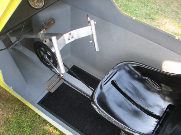
I found these recent picture of a Pedicar on the web. The were taken in Hartford Connecticut, where the Pedicar was manufactured. The vehicle appears to be restored as opposed to being in original condition.


 The body is slightly different from the proceeding pictures in this post. I will assume that the pictures in the post are of a publicity version of the vehicle, and this is one of the 20 vehicles that were manufactured. Notice that the edges of the body are more rounded and the body appears to be slightly simplified in shape. But most interesting is the fact that the wheels are pulled into the width of the body. It looks like the tire track is narrower that the publicity version. If that is the case it would allow the vehicle to pass through narrower spaces. Which is a design improvement. The third picture is of the interior. It is the changes here that convince me it has been restored. Recall that the concept was built around a linear-drive pedal system and it used a five-speed plus reverse transmission. It could have worked with a rotary pedal system, but the photo above does not display the production quality I would expect from Bundschuh. There appears to be no provision for gear changing and the single handbrake is not attached to anything. In addition, it looks like there would be interference between the driver's knees and the steering yoke during pedaling.
P.P.S
I found these recent picture of a Pedicar on the web. The were taken in Hartford Connecticut, where the Pedicar was manufactured. The vehicle appears to be restored as opposed to being in original condition.


Hephaestus


