Reflections on the potential of human power for transportation

Saturday, September 28, 2024

Quadvelo: Finally, after 50 Years, a Worthy Sucessor to the Pedicar


Many of my small number of followers know of my fascination for the 1973 Pedicar that made its debut in the US during the gas crisis. The Pedicar was revolutionary, but unfortunately, less than 20 units were ever built.

The post below goes into depth on the Pedicar's construction.

   https://lefthandedcyclist.blogspot.com/2012/04/pedicar-technology.html

The arrival of the Pedicar started my quest to design my own all-weather pedal-powered commuter vehicle, and I was presumptuous enough to think I could improve on the Pedicar.

My list of requirements for the design is listed below

1.The vehicle should have three or more wheels for stability on slippery surfaces.
2. It should place the rider's head at the height of a typical automobile.
3. It should be narrow enough to comfortably fit in a bike lane. I can be more specific on this. It should fit between barriers spaced 36" apart, so assume a maximal width of 34".
4. It should not overturn when cornering. Assume a tipping resistance of .7 gee.
4. It should be enclosed to protect the rider from the elements.
5. And for traction on slippery surfaces, it should drive at least two wheels.

The Pedicar met all the requirements, except the width being approx. 36" wide. In current dollars the cost was $3620. 

The Pedicar's technical failing was its linear pedal drive. The pedal levers pulled chains that ran over freewheels. This resulted in a constant torque at the wheels. A freewheel on each half-axle acted as a posi-traction differential. It had five forward speeds and a very impressive reverse gear. Braking was with twin discs on the rear wheels. 

It was 82" long with a 58" wheelbase and weighed 125lb. 

The chassis was an "I" shaped aluminum weldment with the long section supporting two crossbeams. There was no formal suspension and shocks were absorbed by the twisting of the central section.

The Quadvelo is 34", 98" long with a wheelbase of 69". It weighs 210lb. with doors and battery. It has a number of similarities to the Pedicar.


 Both used four 20" wheels. The Quadvelo's chassis is made up of a "T" shaped aluminum weldment. Perpendicular carbon-fiber leaf springs support the front wheels at the front of the "T" and longitudinal leaf springs support a transverse beam that, in turn supports the rear wheel axles. The seat can slide along the longitudinal leg of the "T". 


The seat's angles are adjustable and the handlebars are mounted below the seat.


The pedals drive a Sachs RS925 motor.


At the rear axle, the Quadvelo used a nine-speed freewheel cluster attached to a Samagaga differential . Two splined axle shafts are attached to the rear hubs. In the lower left of the picture you can see the longitudinal carbon-fiber leaf spring that supported the axle assembly. Also connected to the axle assembly are two dampers that are connected to an "L" shaped extension of the chassis. Braking is done by four hub brakes all around. 


The carbon-fiber leaf springs that support the front wheels is shown below.


The Quadvelo is 92" long with a wheelbase of 69". The vehicle width is 33.5" Vehicle weight is approx. 210lb and the cost of the basic model with doors is $13,2800.

Overall, I think the Quadvelo is well designed, but I think it could be improved. Looking at the assembled chassis without the body, I think that the wheelbase could be significantly shortened by at least 10" For reference, I am riding a delta trike with a wheelbase of 52"

Another concern is the cost. I don't know who would spend over $10,000 for what is basically an all-weather tricycle, limited to 15mph. If the Pedicar was updated with a derailleur transmission, hub brakes and a crank-mounted motor drive, the present day cost would still be less than $5000. So some of the Quadvelo's complexity should be eliminated to drop the cost.

Of course, the biggest problem with the Quadvelo is that four-wheel pedal assisted vehicles do not qualify as E-bikes in North America. The regulations state the vehicle can not have more than three wheels. 

Now a quad vehicle has 50% more roll-over resistance than a trike having the same track (lateral wheel spacing). So it is difficult to design a trike to meet my design requirements without having it be able to lean into corners. I won't discuss leaning trikes here, since I have written about them ad nauseum in other blog articles. So a quad layout, despite the complexity of another wheel, is a preferred layout for an all-weather, pedal-assisted commuter vehicle.

If E-bike speeds were all limited to 20mph, then I would recommend that four wheels would be allowable and require the width of both three and four wheelers to be 34" or less. Unfortunately, I feel that the 28mph speed limit for class 3 E-bikes is unacceptable with a vehicle as large as the Quadvelo.
Think of the potential damage a 400+lb vehicle could cause if it hit something or someone at 28mph.
Class 1 & 2 E-bikes can go up to 20mph and my experience is that when my leaning trike, that is plenty fast.

Hephaestus 


Wednesday, August 7, 2024

The E-Car-Go, a Compact, Leaning Cargo Trike


I have built five versions of a commuter trike prototype. To reconcile a having a car-height posture with a width that is narrow enough for bike paths, they have all been learnable. To be controlable on slippery surfaces they all had two-wheel drive. With a hub motor in front, the trikes are all-wheel-drive. All these vehicle have the designator EcoVia.

 EV1 and EV4 had tadpole layouts with rear steering. Both suffered from instabilities. EV2 and EV3 were delta trikes. EV3 worked well enough that I use it to run errands in my neighborhood. EV3 used much of the hardware from EV2, which resulted in the design being overly complex.

When EV4 failed last fall, I decided  to fix the obvious defects in EV3 and came up with EV5. Some of the hardware from EV3 and EV4 were reused in version five. Because of its large cargo capacity, EV5 has been renamed "E-Car-Go"

EV3 is shown below.


The EV3's rear wheels are mounted on beams that pivot to facilitate leaning. The pedals drive a jackshaft with a cassette in the middle and freewheels on the ends.  Chains connect the freewheels to fixed cogs on the wheel axles on the other end of the wheel beams. The freewheels act as a positraction differential. The EV3 is  not free-leaning. A lean lever allows for controlled leaning and there is a lean lock that can bias the lean lever force from free to being locked up. Steering is the under-seat type and leaning is controlled by a lever on the left side of the trike. Pulling back on the lever leans left and pushing on the lever leans right. Lean control is very intuitive. Below is the lean-lock that was repurposed from the EV3

Below is the E-Car-Go. The overall length if 80in., the width is 32" and the seat height is 20". 
Numerous improvements have been made in the ECG.


1. To prevent wheel slip form the front motor wheel, a wider tire of 2.125" was substituted for the 1.35" wide rear tires

2. The intermediate bottom bracket, crankset, chainrings and chain where eliminated by connecting the cranks directly to the jackshaft with one chain and an idler.


3. A 1x12 drive was used having a gear range of 26 to 94gear inches.

4. A stiffer scissors joint with .625" bronze bushings was used to support the seat beam.


5. A bicycle shock absorber was substituted for the coil spring of the EV3. Changing the internal pressure of the shock allows for spring-rate adjustment to match rider and cargo weight.

6. The lean angle limit was increased from 17deg  to 20 deg.

The lean control lever is shown below.
Leaning left.


Leaning right
7. Return springs were added to the lean lever


8. The brake modulator linkage, which equalizes rear-wheel braking to keep the trike moving straight when stopping has been improved. It is now symmetric insuring that the cable lengths for each brake are equal and have the same friction.


9. The construction of the wheel-beam assemblies has been simplified.


10. A second transport crate was added below the first crate. The crates have a volume of 1800cu.in.

Below is a sketch of an enclosed version of the ECG with the wheelbase extended to enlarge the cargo carrying capacity.


Hephaestus

8/7/2024


Monday, March 4, 2024

A Full-body Exercise Recumbent: The Omnidyne 3P


My readers will recall that I previous did a post on my experience adding arm power to my Avatar recumbent.

http://lefthandedcyclist.blogspot.com/2012/03/arm-power-and-avatar.html

Now to recap, the Avatar approach used a bolt-on rocking-handlebar and a freewheel added to the left side of the crank axle. Pulling on the handlebars pulled on a chain passing under the crank freewheel moving the pedals forward. A spring attached to the other end of the chain moved the handlebars backward when the pulling force was removed. The linkage connecting the handlebars to the steering was designed to decouple the rocking from the steering.

This arm-power-mechanism worked fine for riding on the flats but was not efficient for climbing hills. Since the handlebars moved at about half the speed of the pedals, the force from pulling on the handle bars was applied every other pedal stroke. On hills this resulted in there being more torque than needed for half the cycle and less for the other half.

The solution was to be able to push the handlebars as well as pulling them. The arms would contribute torque on each  pedal stroke.

 I would need two freewheels to accomplish this and couldn't fit them both on the left side of a single crankset. This meant I would have to add a second bottom bracket with three chainrings on the right side and two freewheels on the left. On the right side, innermost chainring would be connected to a single chainring driven by the pedal crankset.  This would be mounted in front of the second bottom bracket. Back to the right side, the middle and outer chainrings would drive the rear cassette in the conventional manner. 

The presence of a second bottom bracket required that I build a new frame to support it. And I realized that if I mounted the pedals directly over the 16" front wheel, I could shorten the wheelbase of the new bike by 12" when compared to the Avatar. The steering decoupled handlebars would be transferred from the Avatar but modified to facilitate the dual drive.


The freewheels used were the same size as used on the Avatar. Since the force produced by the handlebars with the Avatar was well matched to the pedaling, the goal was to keep things the same for the Omnidyne. The rocking handle bar has two beams attached to it, one on either side of the freewheel  pair. Pulling back engages the outer freewheel while the other freewheel ratchets. Pushing forward engages the inner freewheel while the outer freewheel ratchets. The beams started as the same length used on the Avatar, but since a greater force could be produced pushing compared to pulling, the pushing beam was lengthened. The distal end of each chain is attached to a spring to keep them taught.

As of late I haven't painted the parts and the Omnidyne has not been ridden outside. I like the new motion so much I have been using it as an exercise bike for the last year. I am confident that the push, pull, pedal motion, (3P), will drastically improve the bike's hill climbing.

Hephaestus 


Sunday, September 4, 2022

Transcending the Pedicar: The EcoVia Mk3


                                  The EcoVia Mk2.4, the best packaged, most aerodynamic version.

For those of you new to the blog or those of you that haven't followed it in a while, the EcoVia project was intended to design and build an all-weather ped-electric commuter tricycle. To reconcile having a narrow width and rider height that was visible to motorists, it would incorporate leaning to improve roll-over-resistance, ROR.

The initial concept was a tadpole configuration with pedal-drive to the two front wheels and a steered- motor driven rear wheel. ( I refer to this as the Dymaxion layout in reference to Bucky Fuller's famous Dymaxion Car)

https://www.blogger.com/blog/post/edit/7497191769424400596/839528612731061124

Now there are two ways to control the leaning of a tricycle. The first is free-leaning, where you balance like a bicycle. The second is to control the lean manually in addition to controlling the steering. Rear-steering bicycles are, at best, difficult to ride. A free-leaning rear-steering tricycle has similar issues, so the initial design intent was to control both steering and leaning with the same motion. Since the amount of lean is a function of steering angle and vehicle speed, this approach can only be approximate at best. 

Below is the control mechanism for the EV1.4

Unfortunately, combining leaning and steering can lead to the undesirable phenomenon of bump-steer where, when a steered wheel hits an obstacle, the steering is perturbed unexpectedly.  This occurred during a medium speed test run. I was upside down in the road before I knew what hit me. I pushed the trike back home and never road the EV1.4 again.

After a period of reflection I realized the only thing to do was flip the wheel arrangement around into a delta configuration. With the rear steering gone, the delta trike leaned and balanced like a bicycle. I had my design. Several design iterations followed to drop the bottom bracket height and use a large Q bottom bracket to maximize pedal-wheel clearance. EV2.3 resulted.

I had no problems starting and stopping with the EV2.3 until I added a faring.


 As often as not, I would tip over before getting started of trying to stop. I had a lever that would lock up the leaning, but the trike was not always upright by the time I activated it. So I came up with a no-lean lock lever. If I was only partially leaned over, pulling the lever did two things. It pushed the trike upright and it locked it in that position.


Given the no-lean-lock lever and it's reduction in crashes, I was confident enough to do some speed tests. I was able to comfortably cruise at about 25mph on the flats.  This confirmed the validity of the design concept.

Jerry Onufer, a fellow HPV'er, visited shortly after, and I asked him if he would like to ride the EV2. He declined, saying that a vehicle that mixed being static with balancing would be too difficult for a new rider to master. And there is more than a bit of truth to that. I was riding the EV2 down a highway and forgot that the no-lean-lock was not engaged. I leaned over and weaved across the road. Fortunately there was no traffic or my HPV days would have been over.

So the EV2 was not ready for prime time, and it was back to the drawing board.

I felt that the trike needed to be statically stable and upright for starting and stopping when enclosed in a faring. To address Jerry's concerns, I decided to eliminate free leaning from the design for the EV3. I also added the ability to manually add leaning when executing tight turns.

Six change were incorporated into the EV3.

1. Increase the rear-wheel track from 20" to 30". The static ROR would be 0.45 gees. 
2. Add a lean lever to manually lean the trike +/- 17.5 deg. to increase the ROR to 0.8 gees.
3. Change the wheel diameters from 20" to 16".
4. Change all the brakes from calipers to disks.
5. Lower the bottom bracket height by 6" 
6. Incorporate a geared hub motor to the front wheel.

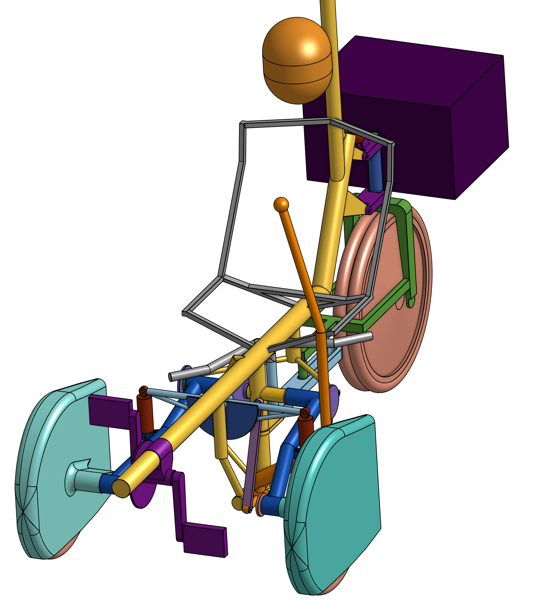
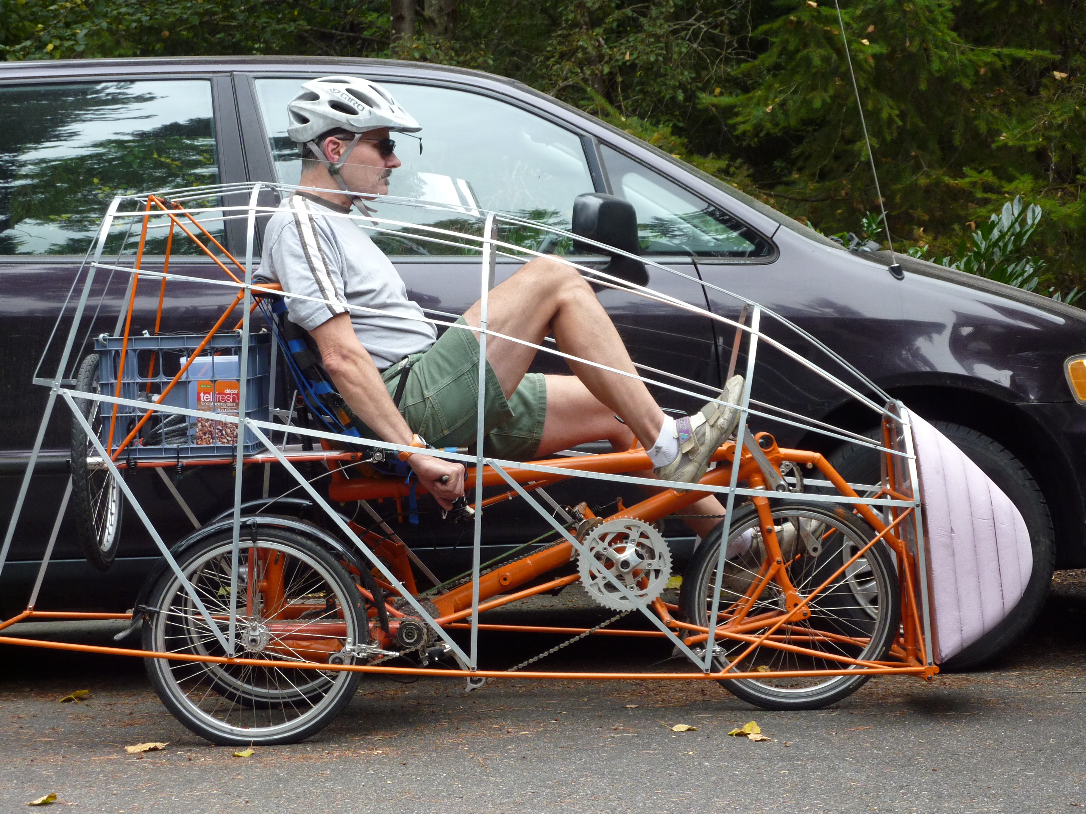
Below is my work-in-progress ped-electric trike, the EV3, shown without its faring.


The initial faring in the picture below is 4" higher at the riders head than the final design.

The EV3 is a delta e-trike with the ability to be statically tilted using a long lever on the riders left side.

The seat height is 20" and with a bottom-bracket height of 14.4", the riding position is very comfortable.  The rider's head at car level. Cranks are 165mm.

Vehicle weight without the faring is 99 lb.  The faring weighs 23 lb.

The battery is 36V which gives a top speed of 15mph. The motor is a geared-hub motor that stops contributing to propulsion at its max speed. The design intent was to have plenty of torque for hill climbing. So much torque, that the front wheel brakes loose if too much throttle is applied when starting. 

For comparison the EV3 has a width of 33"(838mm) and a riders head height of 49"(1245mm)

The EV4 is currently in the design  phase. Because free leaning has been eliminated, I can return to the EV1 tadpole configuration with a Dymaxion layout. The foot-front-wheel interference is removed. The intermediary bottom bracket and its associated chain will be gone. The beam suspension will be replaced by springs in the lean linkage, in addition to adding suspension to the rear wheel. These, and other integrations will significantly simplify construction and reduce weight. 


Wheel pants will streamline the front wheels which will be outboard of the fuselage. In addition the rear-motor wheel will use dual tires to improve traction and insure steering control is maintained in the event that one of the tires goes flat. 


Hephaestus