Reflections on the potential of human power for transportation

Sunday, September 4, 2022

Transcending the Pedicar: The EcoVia Mk3


                                  The EcoVia Mk2.4, the best packaged, most aerodynamic version.

For those of you new to the blog or those of you that haven't followed it in a while, the EcoVia project was intended to design and build an all-weather ped-electric commuter tricycle. To reconcile having a narrow width and rider height that was visible to motorists, it would incorporate leaning to improve roll-over-resistance, ROR.

The initial concept was a tadpole configuration with pedal-drive to the two front wheels and a steered- motor driven rear wheel. ( I refer to this as the Dymaxion layout in reference to Bucky Fuller's famous Dymaxion Car)

https://www.blogger.com/blog/post/edit/7497191769424400596/839528612731061124

Now there are two ways to control the leaning of a tricycle. The first is free-leaning, where you balance like a bicycle. The second is to control the lean manually in addition to controlling the steering. Rear-steering bicycles are, at best, difficult to ride. A free-leaning rear-steering tricycle has similar issues, so the initial design intent was to control both steering and leaning with the same motion. Since the amount of lean is a function of steering angle and vehicle speed, this approach can only be approximate at best. 

Below is the control mechanism for the EV1.4

Unfortunately, combining leaning and steering can lead to the undesirable phenomenon of bump-steer where, when a steered wheel hits an obstacle, the steering is perturbed unexpectedly.  This occurred during a medium speed test run. I was upside down in the road before I knew what hit me. I pushed the trike back home and never road the EV1.4 again.

After a period of reflection I realized the only thing to do was flip the wheel arrangement around into a delta configuration. With the rear steering gone, the delta trike leaned and balanced like a bicycle. I had my design. Several design iterations followed to drop the bottom bracket height and use a large Q bottom bracket to maximize pedal-wheel clearance. EV2.3 resulted.

I had no problems starting and stopping with the EV2.3 until I added a faring.


 As often as not, I would tip over before getting started of trying to stop. I had a lever that would lock up the leaning, but the trike was not always upright by the time I activated it. So I came up with a no-lean lock lever. If I was only partially leaned over, pulling the lever did two things. It pushed the trike upright and it locked it in that position.


Given the no-lean-lock lever and it's reduction in crashes, I was confident enough to do some speed tests. I was able to comfortably cruise at about 25mph on the flats.  This confirmed the validity of the design concept.

Jerry Onufer, a fellow HPV'er, visited shortly after, and I asked him if he would like to ride the EV2. He declined, saying that a vehicle that mixed being static with balancing would be too difficult for a new rider to master. And there is more than a bit of truth to that. I was riding the EV2 down a highway and forgot that the no-lean-lock was not engaged. I leaned over and weaved across the road. Fortunately there was no traffic or my HPV days would have been over.

So the EV2 was not ready for prime time, and it was back to the drawing board.

I felt that the trike needed to be statically stable and upright for starting and stopping when enclosed in a faring. To address Jerry's concerns, I decided to eliminate free leaning from the design for the EV3. I also added the ability to manually add leaning when executing tight turns.

Six change were incorporated into the EV3.

1. Increase the rear-wheel track from 20" to 30". The static ROR would be 0.45 gees. 
2. Add a lean lever to manually lean the trike +/- 17.5 deg. to increase the ROR to 0.8 gees.
3. Change the wheel diameters from 20" to 16".
4. Change all the brakes from calipers to disks.
5. Lower the bottom bracket height by 6" 
6. Incorporate a geared hub motor to the front wheel.

Below is my work-in-progress ped-electric trike, the EV3, shown without its faring.


The initial faring in the picture below is 4" higher at the riders head than the final design.

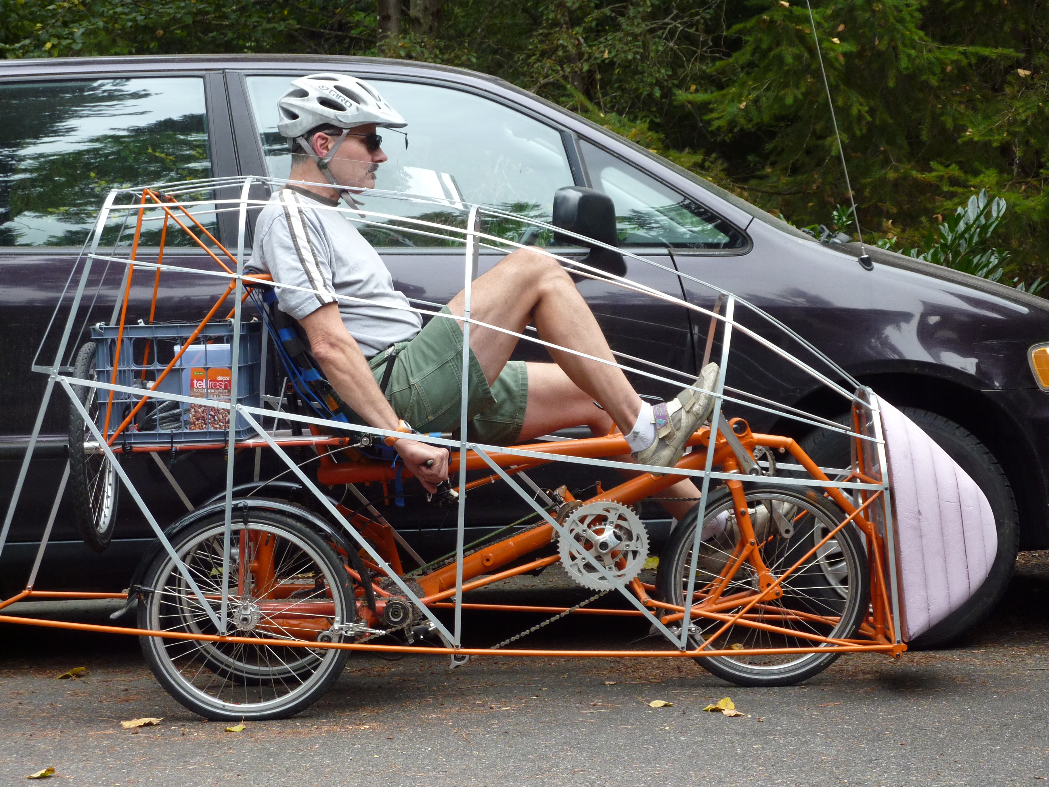
The EV3 is a delta e-trike with the ability to be statically tilted using a long lever on the riders left side.

The seat height is 20" and with a bottom-bracket height of 14.4", the riding position is very comfortable.  The rider's head at car level. Cranks are 165mm.

Vehicle weight without the faring is 99 lb.  The faring weighs 23 lb.

The battery is 36V which gives a top speed of 15mph. The motor is a geared-hub motor that stops contributing to propulsion at its max speed. The design intent was to have plenty of torque for hill climbing. So much torque, that the front wheel brakes loose if too much throttle is applied when starting. 

For comparison the EV3 has a width of 33"(838mm) and a riders head height of 49"(1245mm)

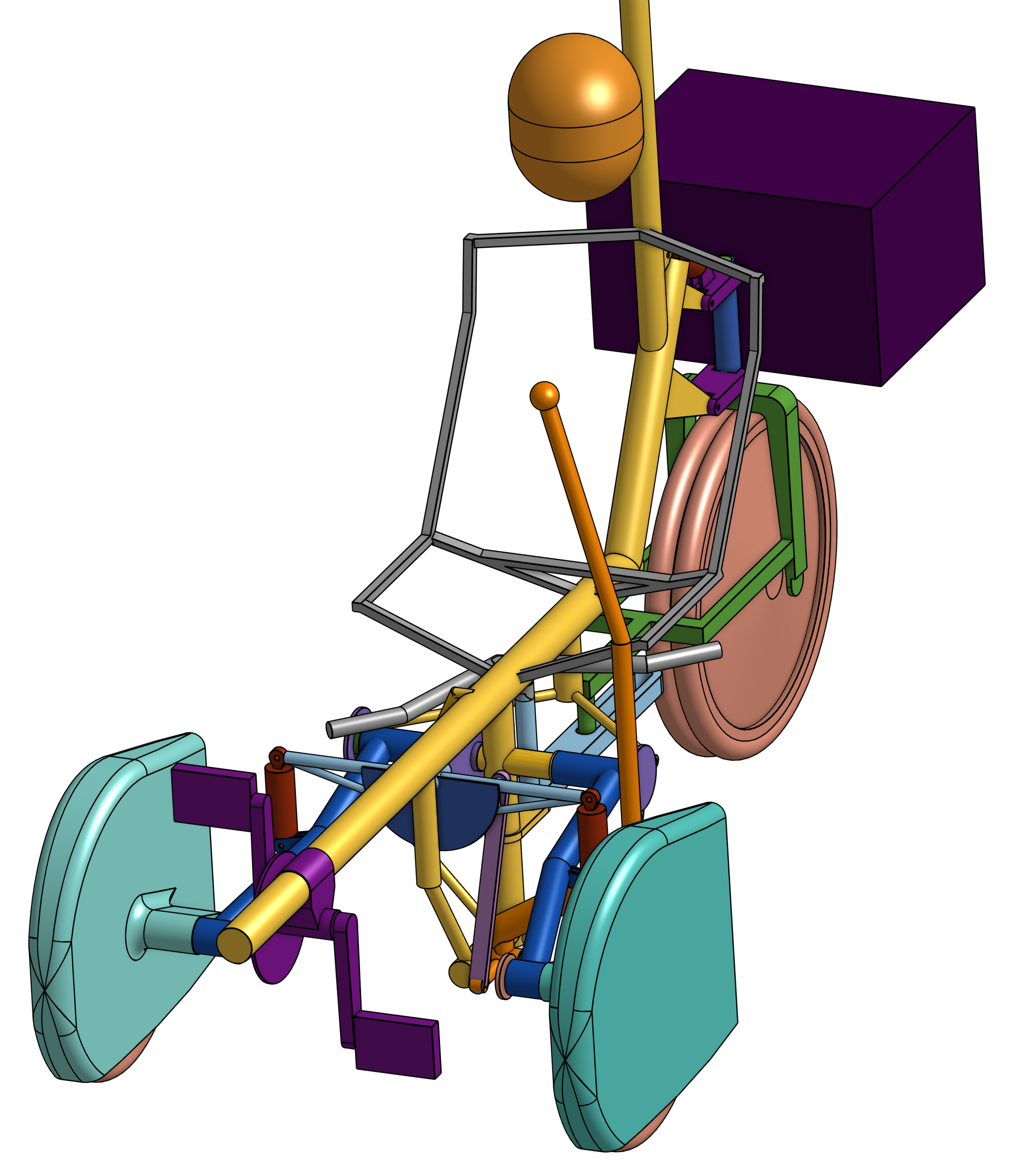
The EV4 is currently in the design  phase. Because free leaning has been eliminated, I can return to the EV1 tadpole configuration with a Dymaxion layout. The foot-front-wheel interference is removed. The intermediary bottom bracket and its associated chain will be gone. The beam suspension will be replaced by springs in the lean linkage, in addition to adding suspension to the rear wheel. These, and other integrations will significantly simplify construction and reduce weight. 


Wheel pants will streamline the front wheels which will be outboard of the fuselage. In addition the rear-motor wheel will use dual tires to improve traction and insure steering control is maintained in the event that one of the tires goes flat. 


Hephaestus


Thursday, August 25, 2022

Dave Wilson and the Improved Safety Bicycle Part 2: Outriggers

Recall from the previous post that the late Prof. David Gordon Wilson reintroduced recumbent bicycles to the public as safer bicycle in the mid-1970s. Interest in recumbent bicycles had languished and a design competition he sponsored in the late 1960s resulted in him building and riding recumbents to work. Ultimately Wilson was featured in a Mobil Oil Ad and he became the face of the recumbent bicycle.

https://www.youtube.com/watch?v=lYbfz4vCczg

Wilson felt that the lower, feet-forward riding position of a recumbent bike would reduce injuries from falls and front end crashes. Wilson advocated under-seat steering to remove the handlebars from the rider's path in the event that the rider was pitched forward during abrupt stops.

He was very cognizant of the fact that the bicycle's simplicity and consequent low cost contributed greatly to its popularity a transportation alternative for many people.

One feature Wilson did not pursue was improving stability on slippery surfaces by adding an additional wheel. Possibility this was because an additional wheel (or two) complicates the construction of the bicycle significantly.

There are at least three conditions that would necessitate needing a statically stable layout instead of a bicycle. The rider has trouble balancing a bicycle. The rider climbs very steep hills that are difficult to balance on. The rider rides on slippery roads and trails.

Now, even though Wilson's recumbent experiments dealt with bicycles, his first edition of Bicycling Science did include a sketch of an enclosed bicycle with outriggers.  

Notice that the outrigger position front-to-back brackets where the cg location is typically located. This insures maximum roll-over resistance for a given track of the outrigger wheels.

Now, I am sure that the intent was that the outriggers would only be used for starting and stopping. But could they be designed so the bicycle could be ridden under transportation conditions with them extended, producing a four-wheel diamond-layout vehicle for improved safety?


I propose to use the outriggers a bit differently than usual. The outriggers would share a common pivot on the frame. They would always stay in contact with the ground. There would be a spring located between them that kept both of them in contact with the ground no matter the flatness of the surface. There would be a spring stop between them that insured they moved together once the spring was compressed.

The outriggers could operate either of two ways. If the common pivot was locked to the frame, the vehicle would act like a fixed four-wheeler. For example when the vehicle was parked or riding on a slippery surface. If the pivot was unlocked it could free lean like a bicycle.

An alternative to free leaning is to have a lever that would control the angle of the frame to the outriggers, allowing leaning to be adjusted by the motion of that lever. Leaning would not be automatic like free leaning but would require the rider to control the amount of lean consciously.

So, if the outriggers are to be in ground contact all the time, why not make the vehicle a quad by providing four regular wheels? In the US and Canada, four-wheel pedaled vehicles are not classified as bicycles or tricycles. The designation is particularly important if the vehicle is electrified and operates on bike paths and bike lanes.

The bike with outriggers I am proposing should be legally considered as a bicycle because the outriggers are like training wheels on a regular bicycle and are ancillary to the basic design.

Hephaestus


Sunday, August 21, 2022

Dave Wilson and the Improved Safety Bicycle Part 1

 We can consider the late Prof. David Gordon Wilson, emeritus professor of mechanical engineer at MIT and author of four editions of Bicycle Science, the technical bible for all-things bicycle, as the father of the modern recumbent bicycle. 

Wilson was a life long bike commuter and environmentalist and rode a small-wheeled Moulton to work. When Wilson launched his bicycle redesign competition in 1967, his goal was to encourage the development of a safer bicycle.

http://lefthandedcyclist.blogspot.com/2019/10/david-gordon-wilson-father-of-modern.html

 With Fredrick Willkie, Wilson developed the Wilson-Willkie recumbent.

The Wilson-Willkie received national exposure when it was featured in a Mobil Oil commercial in 1976.

https://www.youtube.com/watch?v=lYbfz4vCczg

The Wilson-Willkie evolved into the Avatar 1000 and then into the Avatar 2000 which went into production in 1980, being the first commercial recumbent since the Second World War.

Wilson's efforts in recumbent bicycle development duplicated the efforts of inventors in the 1930s to improve on the third generation safety bicycle. These previous efforts were banned from competition by the Union Cycliste Internationale because they felt the aerodynamic improvements of the reclining posture offered riders an unfair advantage.

http://lefthandedcyclist.blogspot.com/2013/12/the-technical-history-of-bicycle-part-3.html 

As it turned out, the Avatar 2000 was too unwieldly to carry up the multiple flights of stairs to his office at MIT,  so Wilson returned to a shorter design, finally ending up with a timing-belt drive that coupled the cranks to an intermediate bottom bracket-chainring assembly.


Wilson felt that two design changes made his recumbents safer that the current bicycles. Lowering the seat height about 12" reduces the injuries associated with the rider falling over and placing the feet forward insures that the rider's feet strike a forward obstruction before the head.  All of Wilson's recumbents use under-seat steering which is not only very comfortable but also safer than upright bars. In the event that the rider was flung forward during hard braking, the rider is not hooked on the bars.
Now, because of what I refer to as the recumbent-packaging problem, Wilson's recumbents came with an undesirable consequence. 

http://lefthandedcyclist.blogspot.com/2012/03/recumbents-and-convergent-evolution.html

The Wilson-Willkie had a very highly loaded front wheel. This resulted in reduced tire life and the possibility of pitching forward in the event of an emergency stop.

The Avatar 2000 had a very lightly loaded front wheel that could loose traction and steering control on slippery surfaces. 


The chart above shows weight distributions for Wilson recumbents and conventional upright bicycles.

Now either of two approaches can be used to achieve a more optimal weight distribution. The first is to raise the bottom bracket above the front wheel to allow the correct wheel spacing without foot-wheel interference. Wilson resorted to this approach on his last prototype designs.

The second is to place the bottom bracket adjacent to the fork crown and use a large Q bottom bracket to maximize pedal-wheel clearance. To prevent chainring-wheel interference an intermediary bottom bracket may be required to achieve a high enough gear ratio. Since Wilson is using an intermediary bottom bracket with his timing-belt drive this would not be an extra complication. This approach would also reduce the wheelbase of the Avatar 2000 by 10in.

This is an approach I have used in the past and would recommend. A near ideal weight distribution front to back of close to 39/61% can be achieved.

So, like Wilson, I would conclude that the recumbent posture makes a safer commuter bicycle than an upright bicycle, as long as the rider's posture is similar to an automobile driver's. And after riding an Avatar 2000 for over 37 years I would add that it is much more comfortable to ride. Despite the above facts, 42 years after the launch of the Avatar 2000, recumbent bicycles are only a small part of the bicycle market, despite the fact that Trek, Cannondale and Giant produced recumbent bicycle models.

One should remember that the bicycle's popularity stems from the fact that it is a relatively simple device which can double the users speed for a given level of effort. Wilson's modifications to create recumbents increased the complexity of the seat and in some cases added an intermediate bottom bracket, but the overall simplicity was maintained.

Hephaestus